FPGA Pong
FPGA Pong is an implementation of Breakout for a Cyclone V FPGA. It implements both the game logic and 3-bit color VGA display drivers. The paddle can be moved using buttons located on the FPGA itself. The player has 3 lives, which are displayed as extra balls in the corner of the screen.
This video shows an almost-complete version of the game. The full version would reset the game and pause for a couple seconds when the ball reached the bottom of the screen. A life would then be deducted when this happens.
Technical Details
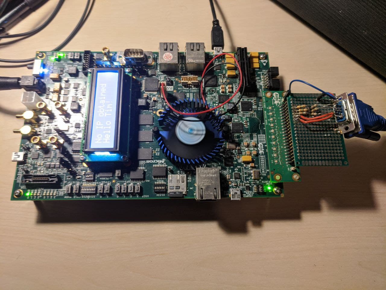
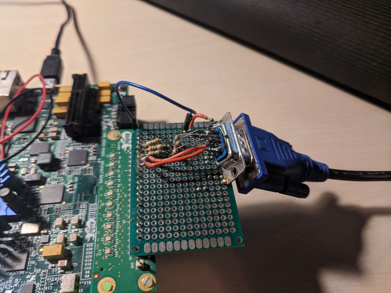
The code is split into two parts, one to drive the VGA signal, and the other to implement the game logic. I used the Altera Cyclone V SoC development board for testing.
The VGA driver ran at 25MHz, which is just below the spec’ed frequency of 25.175MHz. The display I used for testing was tolerant of this lower pixel clock. It will generate the hsync and vsync signals, and output X and Y values for the game logic to use when drawing pixels.
The game logic ran at ~3kHz. The ball’s position is tracked in subpixel units, which allowed for a high clock speed. The blocks are stored in an array of 1-bit registers. These registers are indexed into in order to perform collision detection. The game logic itself is written as a large string of combinatorial logic. Depending on how the logic is laid out onto the chip and the depth of the combinatorial logic is quite large, this could cause visual artifacts like ghosting on the screen.
The game simulated 6-bit color by utilizing dithering. This was used to produce the color of the bricks. The pixels were assigned colors according to a checkerboard pattern, and the parity of this pattern was switched every frame. This provided a reasonably good effect which is only noticeable upon close inspection.