
DogEars
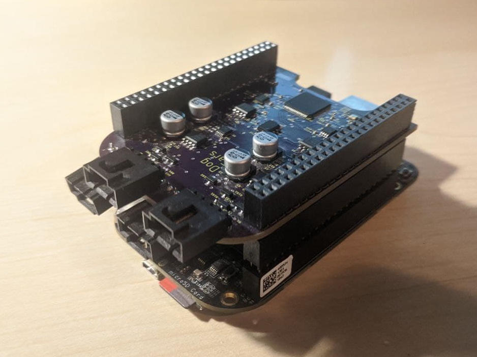
DogEars is a low-cost ADC for the BeagleBone designed for use in sonar applications. The hardware was designed by Steve Kahle and the software is written by Ethan Shea while at the Applied Physics Lab - UW. It can sample up to 4 channels at 144kHz/24bits. There are 4 selectable gain modes, and power can be delivered to active hydrophones. Samples can be acquired in real-time or captured. Applications using the DogEars driver can be written in C++ or python.
Technical Details
Hardware
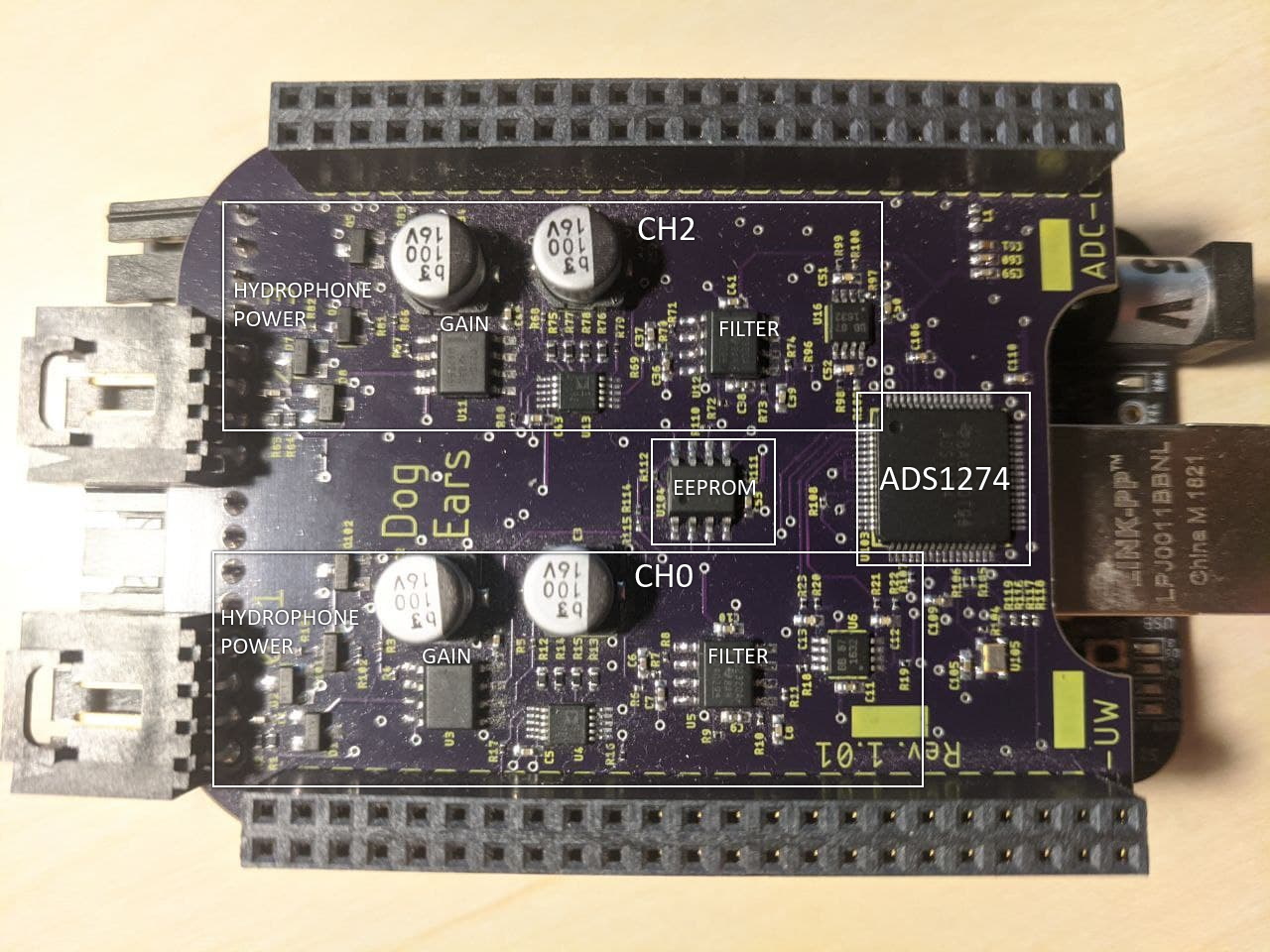
The board is built around the ADS1274 from Texas Instruments. The board is designed as a beaglebone cape. Each input has two gain stages, one fixed at 10db and the other 0-30db in 10db increments, followed by a 40kHz lo-pass filter. Additionally, each input can supply power to an active hydrophone. The gain stages and filters are built using the OPA2320, also from TI.
Software
The driver runs in two locations, on the beaglebone’s main processor and one a remote processor called the PRU (Programmable Realtime Unit). On startup, the driver programs and starts the PRU, then collects data from it by polling a section of shared RAM.
Because of the time-sensitive nature of the communication between the PRU and the ADC, the PRU code is written in assembly. Each PRU instruction executes in 5ns. The beaglebone code is written in C++. There is also a python wrapper which exposes the C++ library to python clients.
The library allows for three sampling modes, streaming and captured or sample. Each sampling mode may format the data as singed integers, unsigned integers, a normalized float, or 24-bit signed integers in a uint32. In streaming, the client passes a callback which is fed each buffer as they arrive. Captured will record a set number of samples. Sample is intended for DC signals, and will simply grab the instantaneous value. Streaming and captured can be used synchronously, or asynchronously. In asynchronous mode the callbacks are called on separate threads from the thread that copies data from the PRU, protecting the driver from user code that runs slowly. The overhead of the driver is ~7% of the AM3358 core in the beaglebone.
In streaming mode, the python wrapper will batch 16 C++ buffers into a single python buffer before making the callback. This keeps the driver overhead to a manageable level, but does increase latency. For this reason, latency sensitive applications must be written in C++. Samples always appear to the python program as numpy arrays of floats.
Moving data between the PRU and ARM Core
The PRU stores the samples in memory designated for the PRU0 and PRU1 cores. This memory is then mmap’d so that the arm core may read the data. This memory is split into two buffers for double buffering. Since the memory is 16KiB in size, each buffer is 8KiB in length. There 4 channels, and each sample is stored in 32 bits, which allows for 512 samples per channel in each of the two buffers.
PRU0 memory + PRU1 memory: 16KiB
Buffer Size: 16KiB / 2 buffers = 8KiB
Memory per channel: 8Kib / 4 channels = 2KiB
Samples per channel in each buffer: 2Kib / 4 bytes = 512 samples
Ideally, the PRU signals to the arm core when it has data available. This could potentially be accomplished through the RPMsg interface (although it seems quite heavyweight). Until such a solution is implemented, the arm core will poll a section in memory containing a monotonically increasing counter, called the buffer number. Any time this number is incremented, a new buffer is available. The parity of this counter is used to determine which buffer is available.
Data in each buffer is laid out first by channel, and then by sample. The entire PRU0 memory will look as follows:
0x0000    0x0800     0x1000     0x1800     0x2000                                      0x4000
  #-------------------------------------------#-------------------------------------------#
  | CH0 BUF0 | CH1 BUF0 | CH2 BUF0 | CH3 BUF0 | CH0 BUF1 | CH1 BUF1 | CH2 BUF1 | CH3 BUF1 |
  #-------------------------------------------#-------------------------------------------#
Each sample is stored as a 32 bit signed integer. This could later be changed to 24 for better performance. Data is placed in the buffer this way to reduce the amount of work needed to be done by the CPU. There’s extra time between each transmission from the ADC that the PRU can do a little more work putting things in the right place.